Vetriebspartner
Sie benötigen Beratung? Unsere bestens geschulten Fachhändler helfen Ihnen gerne bei kleinen und großen Fragen weiter.
Finden Sie einen Händler in Ihrer Nähe
Auswahlhilfe
Die Wahl des richtigen Wechselrichters/Ladegeräts beginnt mit der Auswahl der Modellreihe, die zu den AC-Eingangsanforderungen des Systems, den ESS-Anforderungen und allen Anforderungen für integrierte Solarenergie passt. Die geeignete Version innerhalb dieser Serie wird dann durch Nennleistung, Systemspannung und andere Dimensionierungsüberlegungen bestimmt.
Dieser Leitfaden umreißt die wichtigsten zu berücksichtigenden Punkte, aber die endgültige Systemauslegung und -dimensionierung sollte immer von einem autorisierten Victron-Händler oder -Installateur bestätigt werden. Er behandelt keine fortgeschrittenen Themen; konsultieren Sie für diese bitte einen Händler, folgen Sie unseren Online-Webinaren, Online-Schulungen, nehmen Sie an Schulungen vor Ort teil oder erstellen Sie ein kostenloses E-Learning-Konto auf Victron Professional.
An inverter/charger combines an inverter that converts DC power from the batteries into AC power for appliances, a battery charger, and an automatic transfer function, all in one compact unit.
Victron inverter/chargers use a bidirectional power converter, meaning the same power stage handles both charging the batteries and supplying AC power from them. This allows energy to flow efficiently in both directions.
When an external AC source is connected, it powers AC appliances directly from the grid or shore supply while charging the batteries simultaneously. This allows high-power loads to run without draining the batteries, so the system does not need to be oversized.
If the external supply is disconnected, the unit switches to inverter mode and continues supplying AC power from the batteries without interruption.

This guide does not cover the technical details of how an inverter/charger works. For more detailed information, watch this video.

For systems that don't need grid or generator connection to charge the batteries, a Victron inverter may be a better choice.
Victron inverter/chargers cover a wide range of system sizes and applications, from mobile setups to large off-grid or grid-connected systems. All units are built for professional use, providing dependable power in demanding conditions. Whether used in an RV, a boat, an industrial backup system or a residential energy storage system, the foundation remains the same: solid construction, long service life, reliable continuous and peak power performance, wide battery compatibility, integration within the Victron ecosystem, and easy monitoring and control through the VictronConnect App and the VRM Portal.
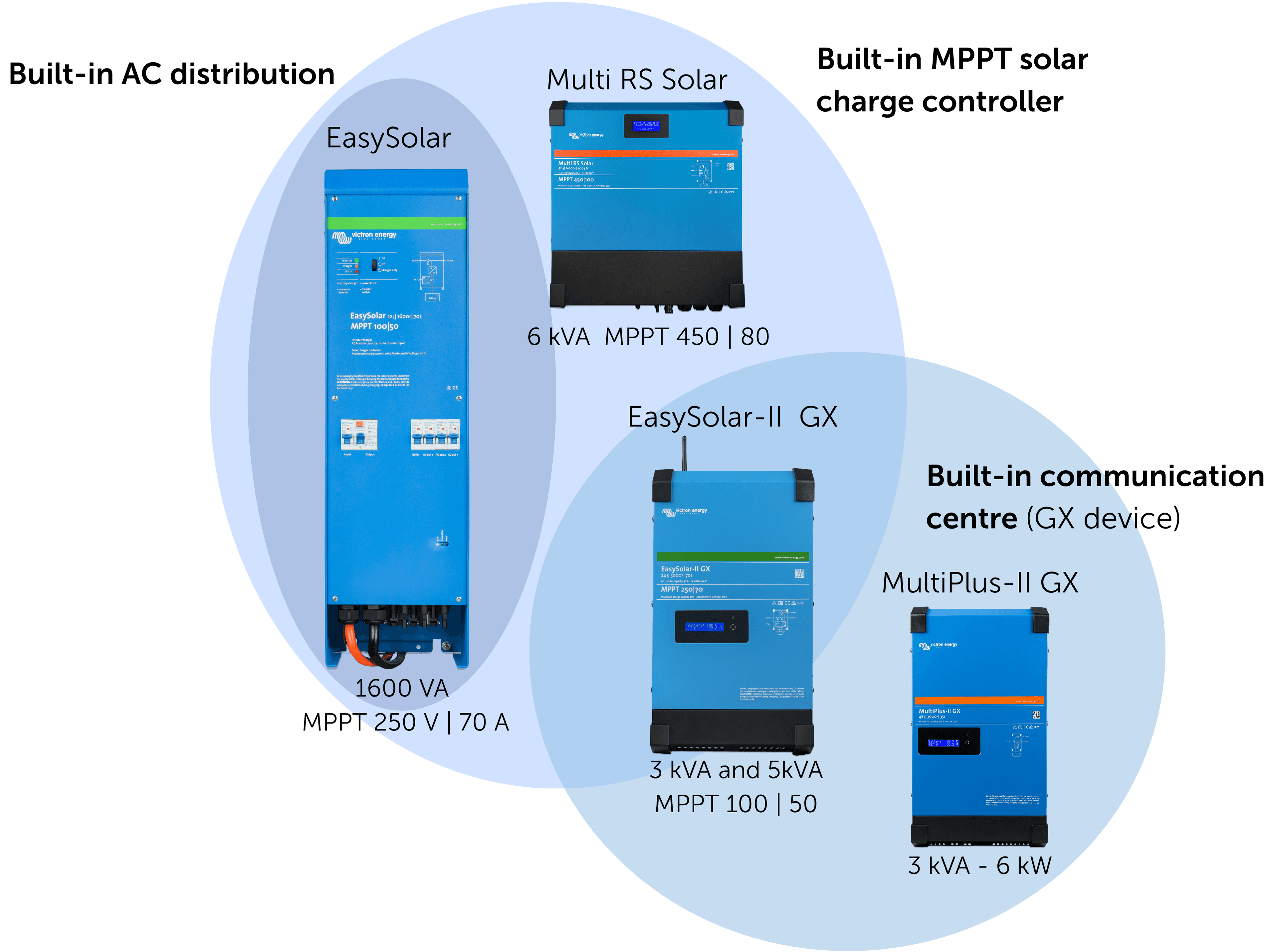
Below is an overview of the Victron inverter/charger ranges:
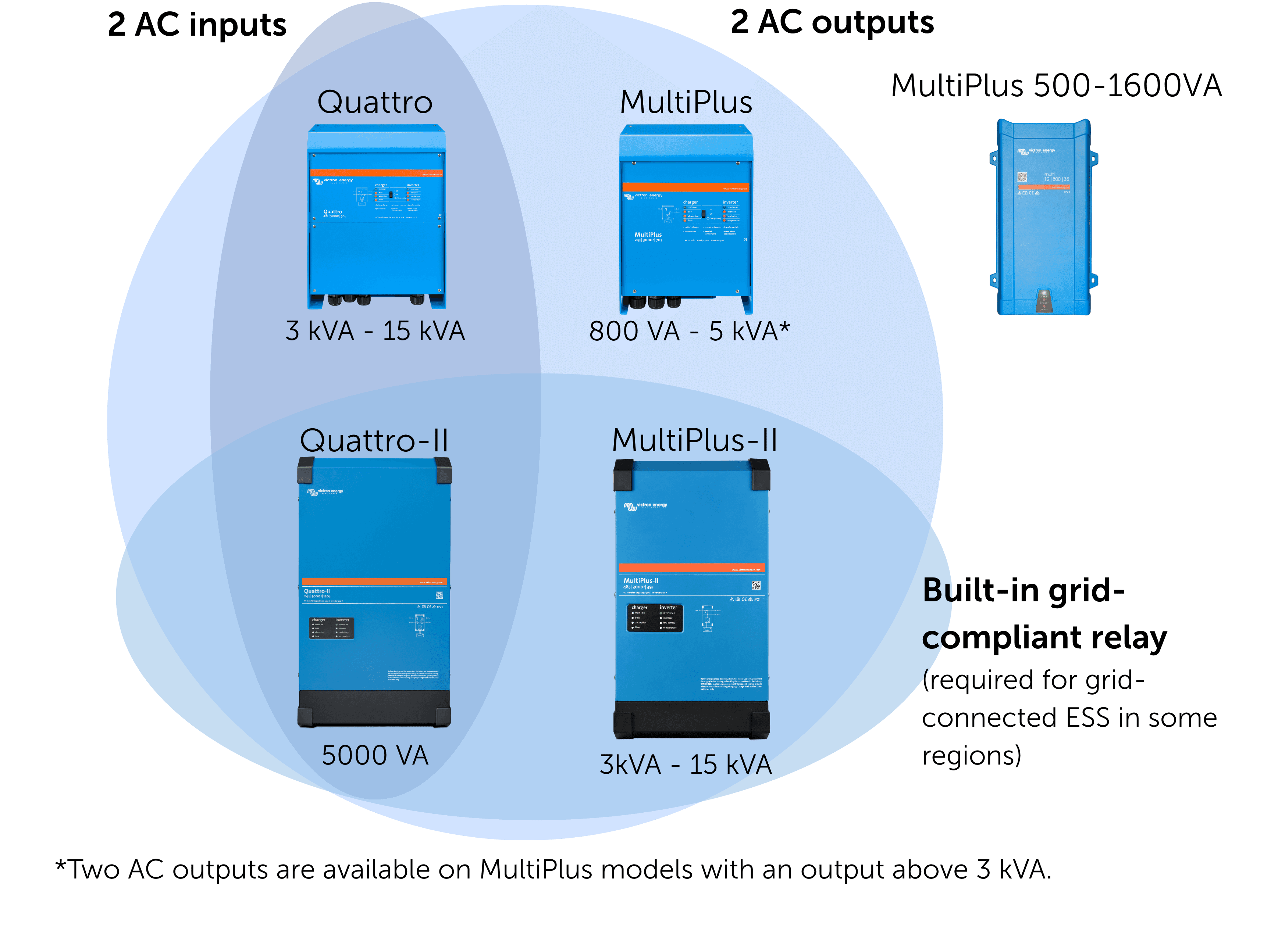
They include the same inverter/charger functionality as the base models, with additional built-in components.
Model |  MultiPlus |  MultiPlus-II |  Quattro |  Quattro-II | GX Models |
Best for | Applications with one AC-input | Energy-storage certified, applications with one AC-input | Applications with two AC-inputs | Energy-storage certified, applications with two AC-inputs | Systems needing built-in monitoring |
AC inputs | 1 | 1 | 2 | 2 | Same as base model |
AC outputs | 1 or 21 | 1 or 21 | 2 | 2 | Same as base model |
PowerAssist | Yes2 | Yes2 | Yes2 | Yes2 | Same as base model |
PowerControl | Yes2 | Yes2 | Yes2 | Yes2 | Same as base model |
ESS Ready | Via external transfer switch | Yes | Via external transfer switch | Yes | Same as base model |
Communication centre integration | External communication centre required | External or built-in (GX version) | External communication centre required | External or built-in (GX version) | Built-in GX communication centre |
Parallel / 3-phase capability | Yes | Yes | Yes | Yes | Same as base model |
Typical use cases | Small systems, vehicles, boats | ESS, home backup, hybrid systems | Generator + grid/shore switching | ESS, generator/grid/shore switching | Remote monitoring or automation all-in-one setups |
1 Models <3000 VA have only 1 AC output.
≥3000 VA models include 2 outputs (transfer + always-on).
2 The 500 VA model does not support PowerAssist or PowerControl; all larger models do.
The MultiPlus 2000 VA is an updated alternative to the former MultiPlus Compact 2000 VA, offering higher efficiency in a taller, slimmer and shallower MultiPlus-II–style enclosure.
Combining an inverter and battery charger in one enclosure enables advanced features such as PowerAssist and PowerControl, making these inverter/chargers suitable for mobile, off-grid, backup and energy storage applications.
In addition to these, all models feature adaptive battery charging to protect battery health, can be connected in parallel or configured for three phase systems, and supports local or remote monitoring and contol when coupled with a communication centre.
This section covers the models within the Victron inverter/charger ranges. This comes down to:

This is the voltage of the service batteries (12 V, 24 V or 48 V). The right choice depends on the size of the system, the voltage of your DC equipment, cable lengths, and how much power the system needs. Higher voltages reduce current, which helps keep cable sizes, weight, and losses lower in larger systems.
12 V is still very common in smaller installations, particularly in marine and vehicle applications. In boats, systems are often 12 V up to around 12–14 metres, after which 24 V becomes more common. Larger or higher-power systems increasingly use 48 V, as it allows more power with lower current and improved efficiency.
Below are a few general reference points, but the actual battery voltage may vary depending on the specific setup. If you’re unsure, it’s best to check with a professional Victron installer.


DC-DC converters are used when different DC voltages are needed. For example, they can convert 12 V DC from batteries for use with 24 V equipment, or vice versa, and allow alternators to charge battery banks.
The required AC output voltage and frequency of an inverter/charger are determined by the regional mains standard where the system operates. Most regions use 230 Vac / 50 Hz, while North America and parts of Latin America use 120 Vac / 60 Hz.
It is important to note that voltage and frequency are not freely interchangeable across all models. As a general rule, 230 Vac / 50 Hz models can also operate at 60 Hz. However, 120 Vac / 60 Hz models cannot be configured to run at 50 Hz, with the exception of a small number of specific models. In the Caribbean, for example, the local standard is 120 Vac / 50 Hz, where a standard 120 Vac / 60 Hz model will not be suitable. Always verify the frequency compatibility of the chosen model before purchasing.
120 V / 60 Hz systems
Common in North America, parts of Latin America, and Japan.
Most appliances and household systems in these regions are built for 120 V, 60 Hz single-phase supply.
230 V / 50 Hz systems
Used across Europe, Asia, Africa, Oceania, and much of Latin America.
Electrical infrastructure and appliances in these regions are designed for 230 V, 50 Hz single-phase supply.
Victron inverter/chargers accept a wide AC input frequency range from the grid or a generator, typically 45 to 65 Hz depending on the model.
When connected to an AC source, the inverter synchronises with the incoming frequency and passes it through to the output.
When no AC input is present, the inverter generates its own output frequency. This is configurable, but the available options depend on the model:
Systems that must supply both 120 Vac and 230 Vac, or convert between them, can be built using Victron inverter/chargers configured in split-phase, together with autotransformers or isolation transformers where needed.
Victron inverter/chargers can be installed and configured to create a split-phase system that provides both 120 Vac and 240 Vac. Transformers can be used to step voltage up or down when required. Isolation transformers provide galvanic isolation between the input and output, while autotransformers do not isolate but can step voltage up or down and create a 120/240 Vac network from either a 120 V or 240 V input.
These configurations are typically used in systems that travel between regions or require multiple voltage levels. Because they involve additional wiring, protection, and regulatory considerations, they should be designed by a qualified installer.

This manual explains the details of designing, installing and configuring three-phase and parallel systems.

The inverter output power must be sized to support the highest expected continuous AC demand of the connected loads, including the combined wattage when multiple AC appliances are used at the same time. This section outlines the key considerations used to determine the required inverter output power.
The inverter output must be sized to support the highest expected continuous AC demand of the connected loads. In smaller or residential systems, this may include appliances such as laptop chargers, TVs, induction hobs, air conditioning units, and kitchen equipment. The same sizing logic applies to larger or more complex installations.
A common mistake is sizing an inverter based only on the highest-power AC appliance used off-grid. To avoid overloading the inverter, it’s also important to consider combined loads, meaning several AC appliances running at the same time.
For example, if a kettle is used off-grid while an induction hob is already on, the inverter/charger must be sized to handle both loads together. In many systems, not all loads are intended to run from the inverter, and non-essential, high-consumption appliances can be excluded.
Making a realistic estimate of which appliances are likely to run at the same time helps ensure stable operation during peak-use periods.


Some appliances draw significantly higher power at startup than their rated load.This start-up surge typically occurs in equipment with moving parts, such as compressors, pumps and motors, or in devices with electronic power supplies such as switch-mode power supplies.
Victron inverter/chargers can deliver peak power exceeding approximately double their continuous rating for short periods. Even so, start-up behaviour must still be considered when sizing the system to avoid overloads.
Most Victron inverter/charger sizes are expressed in VA (volt-ampere). Some newer models are now rated in watts (W) instead. This section briefly explains what VA means and why this transition is taking place.
In an AC system, voltage and current follow a sine wave. If a load is purely resistive, such as a heater or toaster, the current follows the voltage exactly and the waveform stays a clean sine wave. In this case, watts and VA are identical.
However, many real-world loads distort or shift this current waveform in one of two ways:
Displacement: Inductive loads such as motors, compressors and transformers, and capacitive loads, cause the current to shift in time relative to the voltage. The waveform stays a sine wave, but it is no longer in step with the voltage.
Distortion: Nonlinear loads such as battery chargers, variable speed drives and most modern electronics draw current in short pulses rather than as a smooth sine wave. This distorts the waveform itself.
In both cases, the inverter has to handle more apparent power (VA) than the real power (watts) actually consumed by the load. This is why inverter capacity has traditionally been specified in VA.
Today this is changing. Regulations now require most electronic devices to include power factor correction (PFC), which actively shapes the current draw back towards a clean sine wave. As a result, the gap between VA and watts has become much smaller, and newer Victron models such as the MultiPlus 20k and the MultiPlus-II 4k5 and 6k5 are now rated in watts, as this better represents the real usable power available to your loads.

For a more detailed explanation of watts, VA and power factor, see our Wiring Unlimited Book.
Inverter output decreases at elevated ambient temperatures.
Victron inverter/chargers achieve their full continuous rating up to 25 °C; output reduces progressively as temperature rises.
If you need help with calculations or troubleshooting, the Victron Toolkit App can help. It includes tools to calculate cable size and voltage drop, explains all LED codes for Multi and Quattro inverter/chargers, and helps calculate inverter and charger output derating for the expected ambient temperature.

The inverter must be supported by a battery system capable of delivering the required continuous and surge DC current. System voltage (12/24/48 V), conductor sizing, DC protection and BMS must match the inverter’s demands. Recommended pairings of inverter/charger size, battery capacity and system voltage are provided in the datasheets and installation manuals and should be followed to ensure adequate DC-side performance.
Professional installations typically include additional capacity margin to account for temperature derating, future load additions, usage variability and long-term stability.
Selecting the next inverter size up can improve reliability and reduce component stress. If you need more guidance on system sizing, please get in touch with a Victron installer.
When selecting a model within the inverter/charger range, consider:
Victron inverter/chargers support a range of communication ports that enable system monitoring, control and integration with other components.
The primary communication port on MultiPlus, MultiPlus-II, Quattro and Quattro-II models. VE.Bus is used for:
Found on inverter/chargers mostly with the “RS” architecture or all-in-one solar models (such as Multi RS Solar). VE.Can supports:
Found on RS series inverter/chargers, mostly to connect to a GlobalLink communication centre.
Please also check the communication centre section.
All Victron inverter/chargers can be connected to communication centres enabling VRM remote management, control and integration or to a bluetooth dongle which enables VictronConnect, but not always out-of-the-box:
VictronConnect can be enabled by adding a VE.Bus Smart (Bluetooth) dongle for local monitoring, or by connecting a communication centre to enable VRM - remote management portal which enables VictronConnect-Remote for remote access (in that scenario, the data is shared through the communication centre and not via bluetooth). Note that the port can only be used for either the dongle or the communication centre.
Experience the power of
With the most current free-to-use monitoring solutions on the planet you can manage it all from anywhere in the world.
More than 1 million
users worldwide
Works
with
Sie benötigen Beratung? Unsere bestens geschulten Fachhändler helfen Ihnen gerne bei kleinen und großen Fragen weiter.
Finden Sie einen Händler in Ihrer Nähe
Sehen Sie sich unsere Support-Ressourcen an oder wenden Sie sich für speziellen Support, Reparaturen oder Garantieanfragen an Ihren Originalhändler.
Support
Lesen Sie mehr über unsere branchenführende 5-Jahres-Standardgarantie und unseren weltweiten Reparaturservice.
Garantie


©Victron Energy 2026
