6. Controlling depth of discharge
Several mechanisms decide how deeply the battery is allowed to discharge, and they act together. BatteryLife manages the minimum SOC over time, the dynamic cut-off sets the voltage at which the inverter stops as a function of discharge current, and sustain protects the battery once it is empty. This chapter explains each of them, and the reason codes shown while any of them is active.
6.1. BatteryLife
Purpose
In a system where the battery is used every day, there are times when daily energy consumption exceeds the daily solar production. This happens during poor weather, in the winter months, or when the PV array is undersized relative to the loads.
During these periods, the battery state of charge falls a little further each day until it reaches the configured minimum SOC. Without intervention, the battery would then remain at or near this low state of charge for an extended period. Operating a battery at a prolonged low state of charge can reduce battery lifetime, cause the state-of-charge estimation to drift, prevent the regular full charge that some lithium cells need to stay balanced, and leave little reserve capacity for a grid failure.
How it works
BatteryLife automatically manages the minimum allowed state of charge so that the battery is regularly recharged to a high level.
If the battery does not reach a sufficiently high state of charge during the day, BatteryLife takes this as a sign that more energy is being consumed than solar PV is replacing, and raises the minimum SOC by 5% for the following day. Raising the minimum SOC reduces the amount of energy drawn from the battery overnight, so more of the load is supplied by the grid, and the battery starts the next day at a higher state of charge. This continues, 5% per day, until the available solar energy is enough to recharge the battery to at least 85%.
When solar production recovers and the battery reaches 95% state of charge, BatteryLife begins lowering the minimum SOC again, by 5% per day, until it returns to the configured value. More battery capacity then becomes available for overnight use once more.
Example
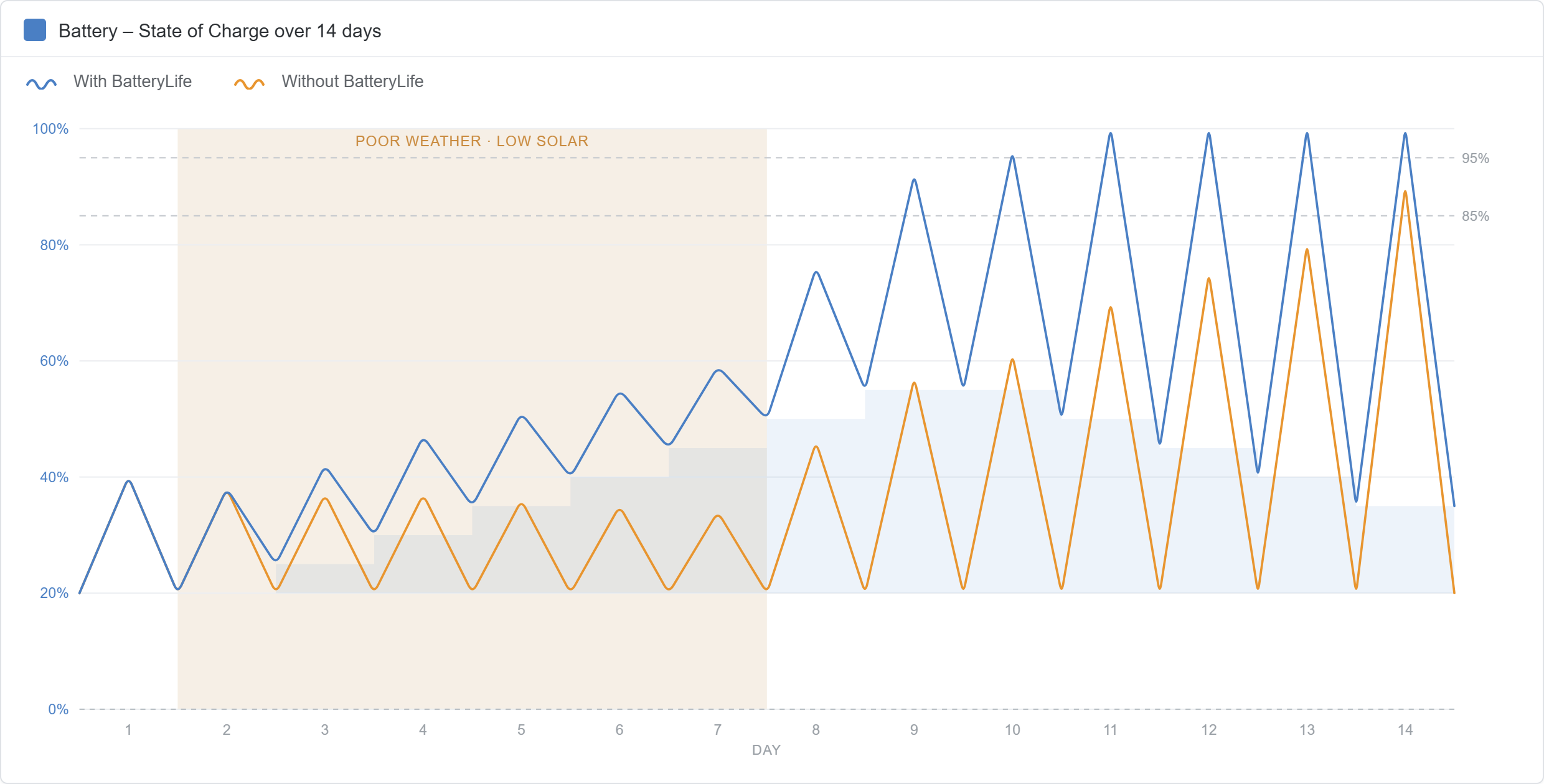
The following example illustrates how BatteryLife behaves over a period of poor weather, assuming a configured minimum SOC of 20%.
During the energy-negative days, the battery repeatedly fails to reach 85% by the end of the day. BatteryLife therefore raises the minimum SOC by 5% each day, taking it from 20% up to 55%. As the minimum SOC rises, the battery is discharged less overnight, more of the load is supplied by the grid, and the battery rests at a progressively higher state of charge.
When solar production recovers and the battery again reaches 85%, the daily increase stops. Once the battery reaches 95%, BatteryLife begins lowering the minimum SOC by 5% each day, from 55% back down to 35%, and onward to the configured 20% over the following days. More battery capacity becomes available for overnight use as the minimum SOC returns to its configured value.
BatteryLife therefore keeps the battery operating within a healthy charge range even when solar energy is temporarily insufficient. Frequent BatteryLife intervention is a sign that daily consumption is regularly exceeding the available solar generation.
 |
BatteryLife states
The current BatteryLife state is shown in the ESS menu and reflects what the system is doing at any moment:
Self-consumption: normal operation. The battery is discharged to supply the loads down to the Active SOC limit.
Discharge disabled: the battery has reached the Active SOC limit and is no longer discharged for self-consumption. Discharging resumes once the SOC rises 5% above that limit.
Slow charge: the battery has remained below the Active SOC limit for more than 24 hours. The system slowly charges it from the grid back up to that limit, to protect the battery from prolonged low SOC.
Sustain: the inverter/charger has entered sustain mode after the battery reached the dynamic cut-off voltage during discharge. See Dynamic cut-off and Sustain.
Recharge: the SOC has fallen more than 5% below the configured minimum SOC, and the system recharges the battery from the grid until it returns above that level.
6.2. Dynamic cut-off
Dynamic cut-off determines when the system stops discharging the battery, based on battery voltage. Rather than using a single fixed low-voltage threshold, it takes the current being drawn from the battery into account.
How it works
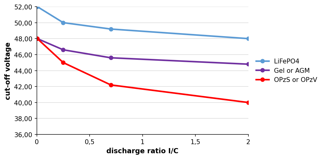
The voltage at which the system stops discharging depends on the discharge current. At high discharge currents the cut-off voltage is lower; at low discharge currents it is higher. The cut-off voltage is defined at four discharge ratios, and the default values depend on the battery type:
Discharge ratio | LiFePO4 (16S)(1) | LiFePO4 (15S) | Gel or AGM(1) | OPzS or OPzV(1) |
|---|---|---|---|---|
0,005 C | 52,00 V | 48,80 V | 48,00 V | 48,00 V |
0,25 C | 50,00 V | 46,90 V | 46,60 V | 45,00 V |
0,7 C | 49,20 V | 46,10 V | 45,60 V | 42,20 V |
2 C | 48,00 V | 45,00 V | 44,80 V | 40,00 V |
Note
(1): The values are for a 48V system. For a 24V system, divide them by two; for a 12V system, divide them by four.
This compensates for the internal resistance of the battery. Under load, the battery's terminal voltage drops in proportion to the current drawn and its internal resistance, so a fixed voltage threshold would misjudge the true state of the battery. By adjusting the cut-off voltage to the current, dynamic cut-off makes battery voltage a more reliable indicator of when the battery is becoming critically discharged.
The discharge-current-versus-cut-off-voltage curve is configured per battery type in the ESS Assistant and can be adjusted there.
 |
Notes
Dynamic cut-off is most useful for batteries with high internal resistance, such as OPzV and OPzS. It is less significant for LiFePO4 batteries, which have low internal resistance; their curve of discharge current versus cut-off voltage is much flatter.
The three DC input low parameters on the Inverter tab (shut-down, restart, and pre-alarm) are not used. They are overridden by the dynamic cut-off levels and the corresponding restart levels, all configured in the ESS Assistant.
Dynamic cut-off is active both when the grid is available and during a grid failure, when the system is in inverter mode.
6.3. Sustain
Purpose
Sustain mode prevents the damage caused by leaving a battery in a deeply discharged state. After the battery has been flagged as discharged, sustain mode holds the battery at a safe voltage rather than allowing it to sit empty.
How it works
Sustain mode is entered after the battery has been flagged as discharged. Either of the following conditions triggers it:
the battery voltage has fallen below the dynamic cut-off level, or
a low-cell signal is received from the VE.Bus BMS.
While sustain is active, the battery voltage is maintained at the sustain voltage level. The level depends on the battery type and the system voltage:
12V system | 24V system | 48V system | |
|---|---|---|---|
Lithium batteries | 12,5 V | 25 V | 50 V |
Other batteries, first 24 hours | 11,5 V | 23 V | 46 V |
Other batteries, after 24 hours | 12,5 V | 25 V | 50 V |
If the battery voltage falls below the sustain level, the battery is charged back up to it using power from the grid when necessary. The maximum charge current used for this is 5 A per unit, regardless of system voltage. Excess solar power is also used for charging.
Sustain mode is exited once solar charging has raised the battery voltage above the sustain level, by 0,1 V in a 12V system, 0,2 V in a 24V system, or 0,4 V in a 48V system. Normal operation then resumes, with the battery supplying power when insufficient energy is harvested from the PV array.
6.4. Battery reason codes
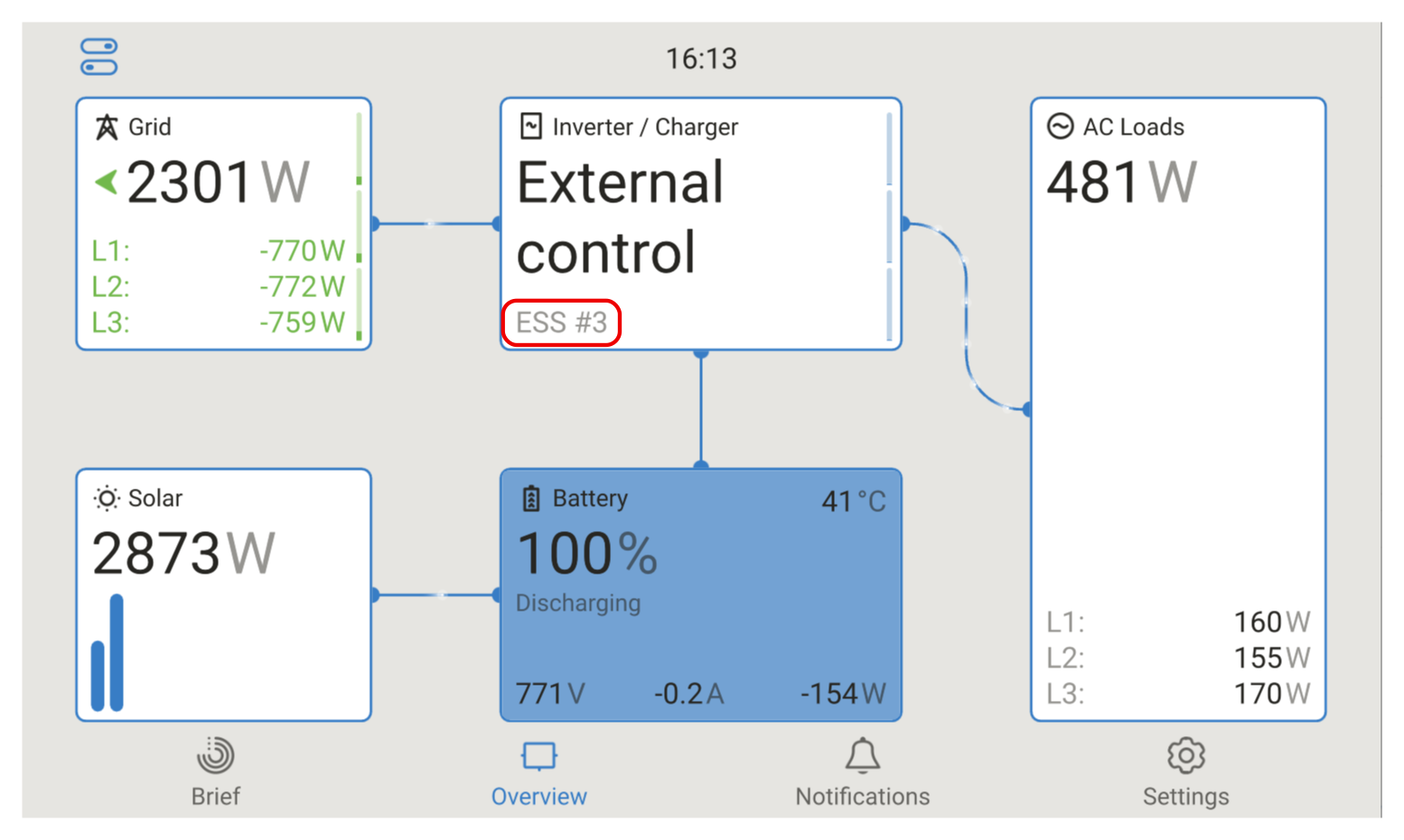
In addition to the charger states (Bulk, Absorption and Float), the system shows Discharging and Sustain reason codes. These appear on the Overview page of the GX device and give at-a-glance information on why the battery is being charged or discharged, or why it is not.
Reason codes: The reason codes and their meanings are:
|  |