5. Configuration
Configuration turns the installed hardware into a working energy storage system. It happens in two places: VEConfigure, which adds the ESS Assistant to the inverter/charger, and the ESS menu on the GX device, which holds the operating settings. This chapter follows that order, starting with firmware and the Assistant, then each setting in the ESS menu, and ending with the PV inverter settings needed for zero and limited feed-in.
5.1. Update to latest firmware
Update all system components to the latest firmware version:
GX devices: Venus OS v2.15 or newer.
Older Color Control GX units on v1.74 require a one-time manual upgrade, which cannot be done automatically. Instructions are in Upgrading a CCGX to v2.00.
Multi, MultiPlus or Quattro: Firmware version xxxx422 or newer. The inverter/charger can be updated in two ways:
Using VictronConnect, described in the VE.Bus configuration guide.
Using remote VE.Bus firmware updates, described in the Remote VE.Bus firmware updates guide.
Solar charge controllers, battery monitors, energy meters and other Victron products: Update to the latest firmware version. Refer to the product's user manual for instructions.
5.2. VEConfigure / ESS Assistant
The following settings must be made in VEConfigure before the system will operate correctly. For general guidance on using this tool, see the VEConfigure manual.
Grid tab: configure the country/grid code.
A password is required, available from the supplier. See VEConfigure: grid codes & loss of mains detection for more information.
Note
Where this setting is left as None, the system will not supply battery energy to support local AC loads while the grid is connected. It must be changed even where there is no intention to export DC energy to the grid.
Virtual switch tab: do not use VS.
This enables adding an assistant.
Assistants tab: add the ESS Assistant.
Under the Assistants tab, add the ESS (Energy Storage System) Assistant and click on the Start assistant button. Read the text on the Welcome page carefully, and make sure the notes and remarks are understood before proceeding. The Assistant then prompts for details about the battery, and about whether an AC-coupled PV inverter is connected to the AC-Out side of the inverter/charger. Answer the prompts according to the system.
See How to add an Assistant for the full procedure.
General tab.
Select the system frequency.
Adjust the AC input current limits based on the grid connection. Note that the current limiter applies to both directions of current flow.
The dynamic current limiter is ignored when the ESS Assistant is installed.
The ESS Assistant activates the integrated battery monitor of the inverter/charger. Leave it enabled even if a BMV or an intelligent battery connected via CAN-bus is present in the system.
Inverter tab.
Adjust inverter output voltage.
The DC-input low shut-down, restart and pre-alarm levels on the Inverter tab do not apply. They are ignored when the ESS Assistant is installed, as further explained in Dynamic cut-off.
The PowerAssist setting in VEConfigure is disabled and ignored when the ESS Assistant is installed.
Charger tab: verify the charge settings.
The ESS Assistant will already have selected the correct battery type and disabled Storage mode. Verify the remaining settings and change where necessary: charge voltages and maximum charge current.
Note
In systems with the ESS Assistant installed, the MPPT solar chargers follow the charge curve set in VEConfigure. The charge parameters configured in the solar chargers themselves are ignored.
General notes
PV power from a grid-tie inverter, whether connected on the AC-In or the AC-Out side, is used to charge the battery through the inverter/charger. Charge current and other charge parameters are configured on the Charger tab in VEConfigure.
Keep the lithium-batteries checkbox on the Charger tab consistent with the battery type selected in the Assistant.
When using a VE.Bus BMS with a Multi Compact, check the DIP switches: DIP switch 1 must be on, and DIP switch 2 must be off.
Low battery warning levels
The low-battery warning becomes active when the battery voltage drops below the dynamic cut-off level plus the restart offset, which defaults to 1,2 V for a 48V system. Like the cut-off voltage, this warning level is dynamic.
There is no hysteresis: the warning clears as soon as the voltage rises again.
During this warning (also called a pre-alarm), the red LED on the inverter/charger blinks, and the GX device can optionally show a notification. In most systems it is recommended to disable this notification on the GX device.
Note
The low-battery warning pop-up on the GX device is disabled from the inverter/charger menu: select Setup, then Alarms, and set the Low DC voltage alarm to Alarm only.
5.3. AC System
Before configuring the ESS menu, set up the AC system so the inverter/charger knows what is connected to each AC input and where the loads are located. These settings are found under Settings → System Setup → AC System.
AC input 1: Set the role of the first AC input: Not available, Generator, Grid, or Shore power. Set the input to Generator when a generator is connected. The system will then enable generator charging and load the generator correctly while it is running. Additional configuration is required to complete the setup of these options. | 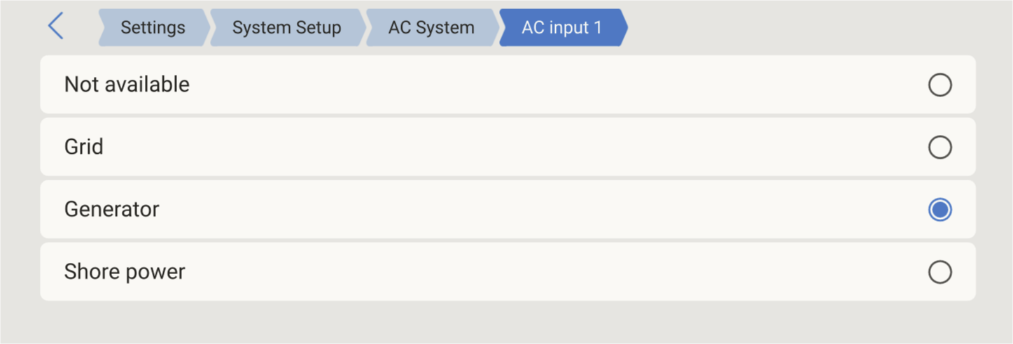 |
AC input 2: Set the role of the second AC input, using the same options as AC input 1. On a Quattro, AC-In 1 has priority over AC-In 2, so the usual arrangement is the grid on AC-In 1 and the generator on AC-In 2. Reverse it, wiring the generator to AC-In 1 and the grid to AC-In 2, only where the generator must take priority over the grid, which allows forced generator intervention even when the grid is available. | 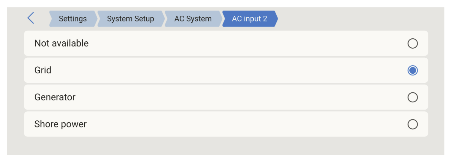 |
Note
Only the Quattro has two AC inputs. This setting does not apply to inverter/chargers with a single AC input, such as the MultiPlus.
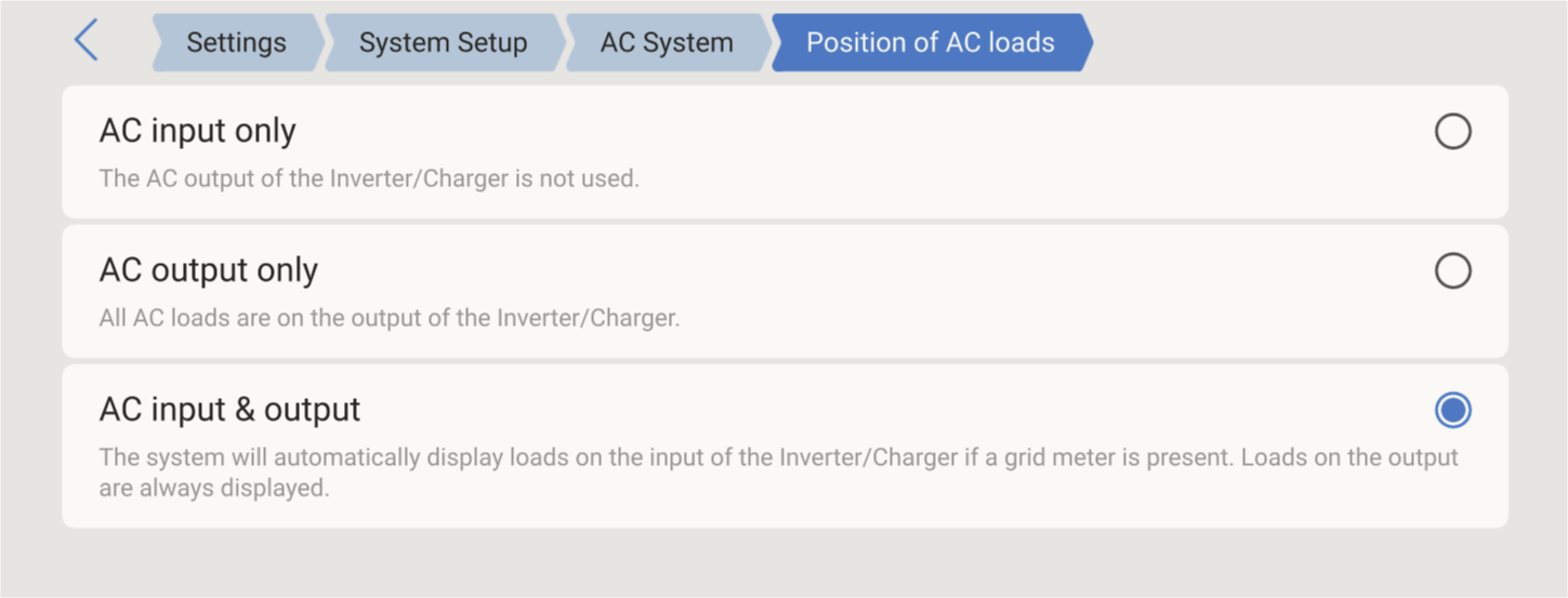
Position of AC loads: Tell the system where the AC loads are connected relative to the inverter/charger, so they are displayed and accounted for correctly:
|  |
Monitor for grid failure: When enabled, the system monitors for loss of the AC input and triggers an alarm if it is detected. The alarm clears when the AC input is reconnected. | 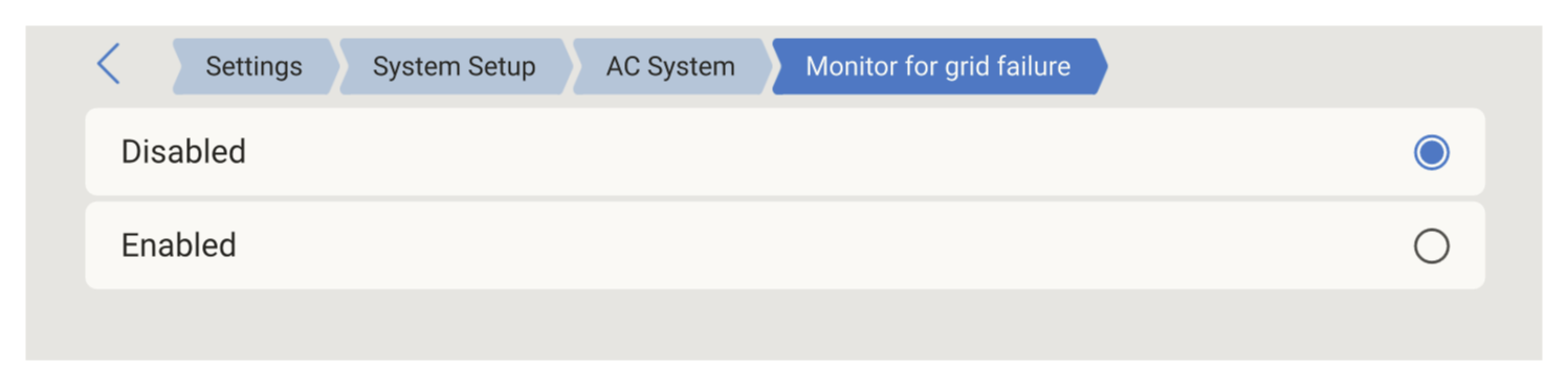 |
5.4. Mode
The Mode setting determines the overall strategy the system uses to manage the battery, grid, and solar. It is found under Settings → System Setup → ESS → Mode. Four modes are available.
Mode: Select the operating strategy for the system. Keep batteries charged The battery is discharged only during a failure of the utility grid. Once the grid is restored, the battery is recharged from the grid, and from solar when available. Use this mode where the battery's primary purpose is backup rather than self-consumption. Optimized with BatteryLife and Optimized without BatteryLife When excess PV power is available, it is stored in the battery. That stored energy is used later to power the loads when there is a shortage of PV power. The two Optimized modes differ only in whether the BatteryLife algorithm is active:
External control The ESS control algorithms are disabled. Use this mode where the system is driven by an external controller running its own control loop. | 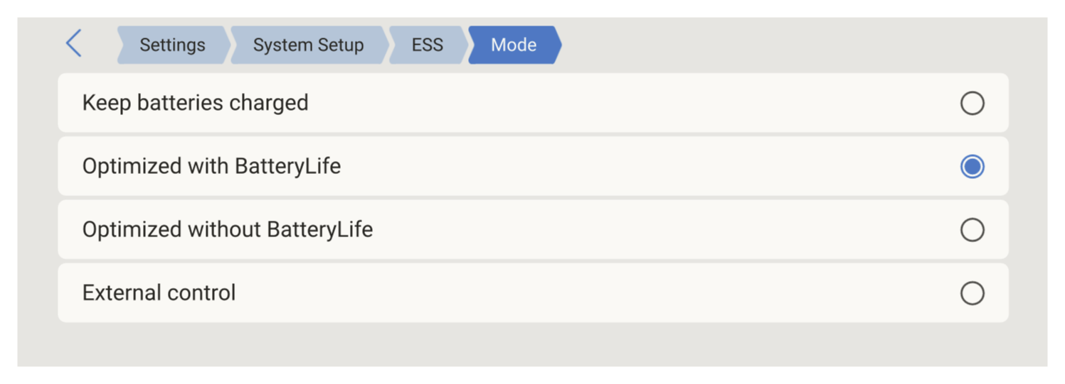 |
5.5. Grid metering
Grid metering: Selects how the system measures grid power exchange. Leave this at 'Inverter/Charger' if no external grid meter is used. Set it to 'External meter' only when a supported external energy meter is actually installed in the system. In a system without a Victron energy meter, all loads and any grid-tie inverters must be installed on the AC output. | 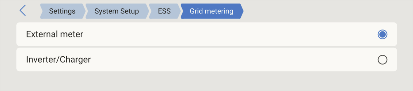 |
Note
If Grid metering is set to External meter without an external meter installed, the battery will not charge from the grid, even when a positive grid setpoint is configured.
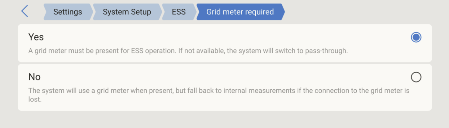
Grid meter required: This option becomes available only when Grid metering is set to 'External meter'. It sets how the system responds if the external grid meter is lost.
|  |
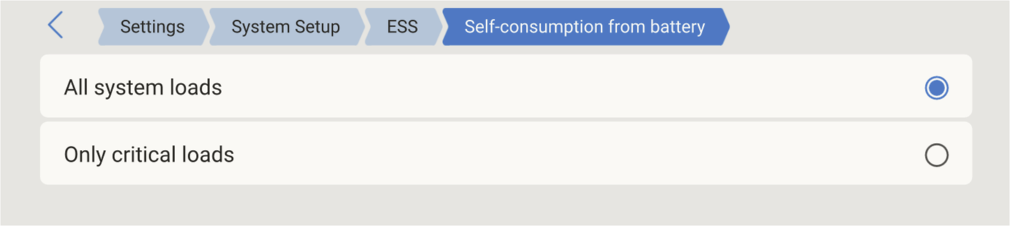
5.6. Self-consumption from battery
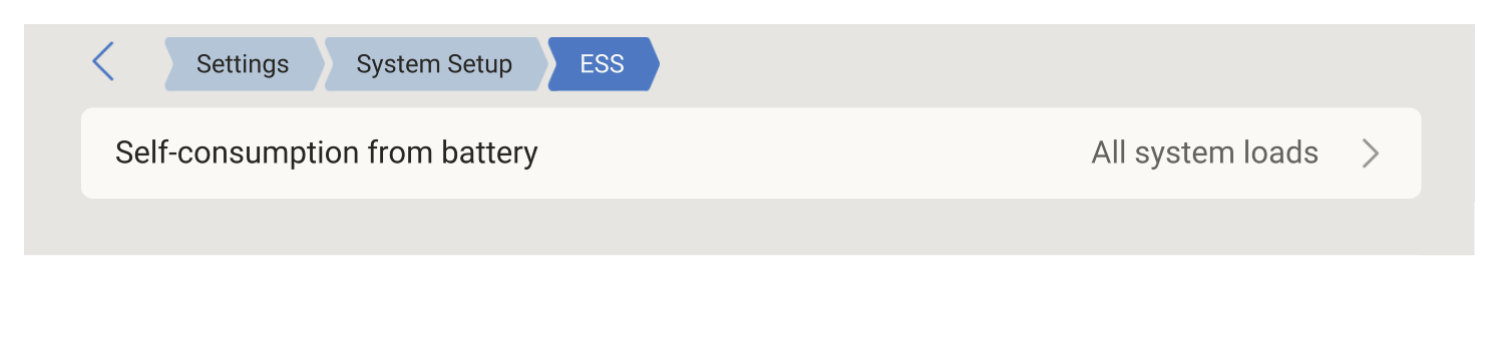
Determines whether the battery is used to supply loads on the AC-In side of the inverter/charger while the grid is connected. It has an effect only when loads are present on the AC-In side; in a system where all loads are on the AC-Out, there is nothing on the AC-In for it to act on.
Self-consumption from battery:
|   |
Note
For the battery to supply AC-In-side loads, Position of AC loads must be set to include the AC input (see AC System).
5.7. Multiphase regulation
Multiphase regulation: Defines how the system interacts with the individual phases in an installation with a three-phase connection to the utility grid. It has no effect on single-phase systems, and no effect when Mode is set to Keep batteries charged.
For a full explanation, including worked examples and notes on charge current and energy meters in three-phase systems, see Multiphase regulation - further information. | 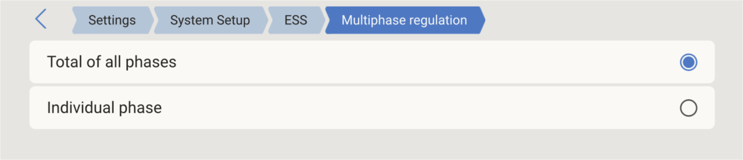 |
5.8. Minimum SOC and Active SOC limit
Minimum SOC (unless grid fails): The configurable minimum state of charge. While the grid is present, the system supplies loads from the grid once the SOC has fallen to this setting, preserving the remaining capacity as a reserve. The exception is a grid failure: when the grid has failed and the system is in inverter mode, the battery continues to discharge below this value to keep powering the loads. In Optimized with BatteryLife mode, this is the configured floor; BatteryLife may temporarily raise the effective limit above it (see Active SOC limit below). In Optimized without BatteryLife mode, this value is used directly and is not adjusted. | 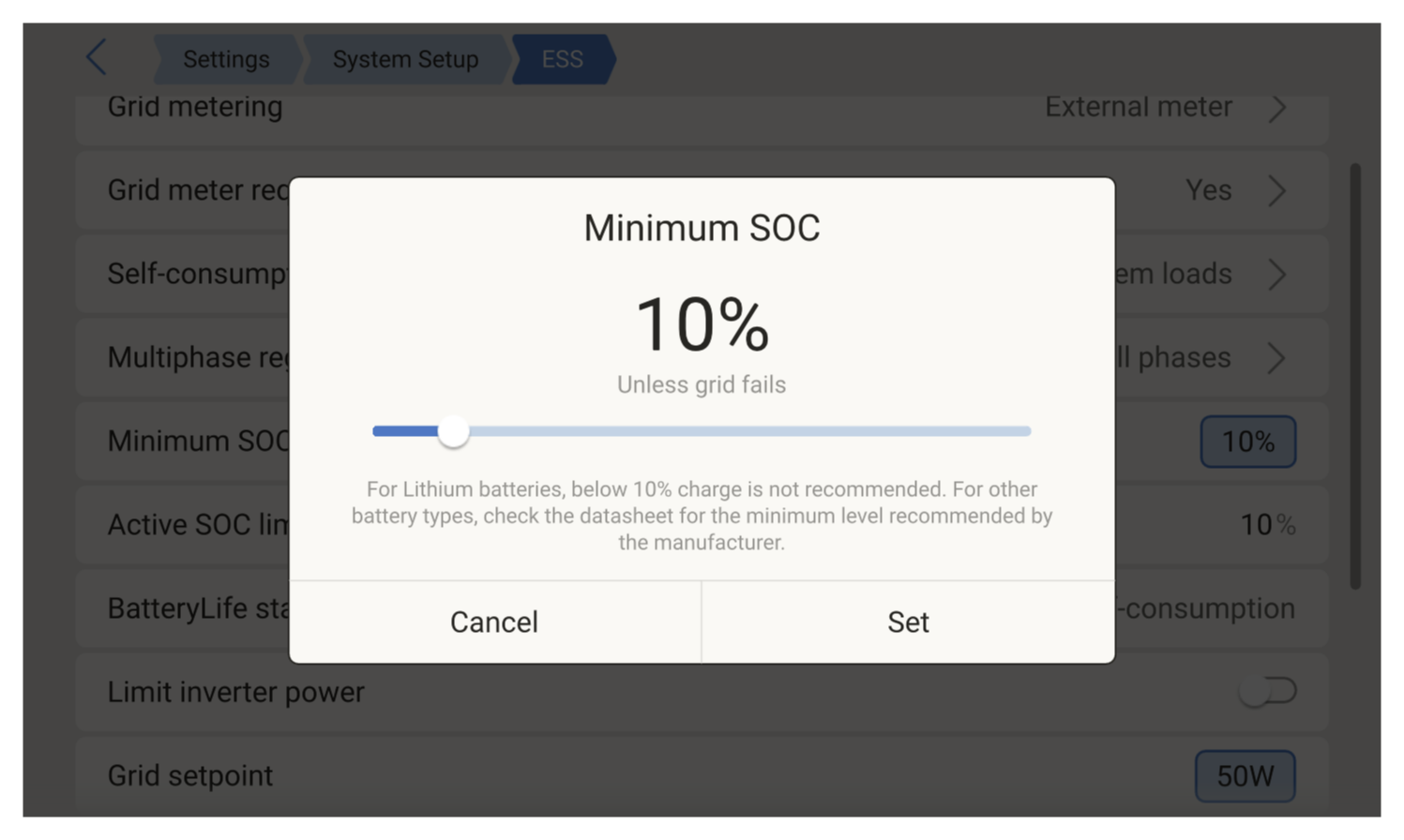 |
Active SOC limit: Shows the minimum SOC limit currently in force. This is only relevant in Optimized with BatteryLife mode, where BatteryLife dynamically adjusts the working minimum SOC day by day. The Active SOC limit is therefore the value BatteryLife is applying right now, which may be higher than the configured Minimum SOC. It represents the maximum usable capacity of the system and will never be more than 80%. See BatteryLife for how this value changes. | 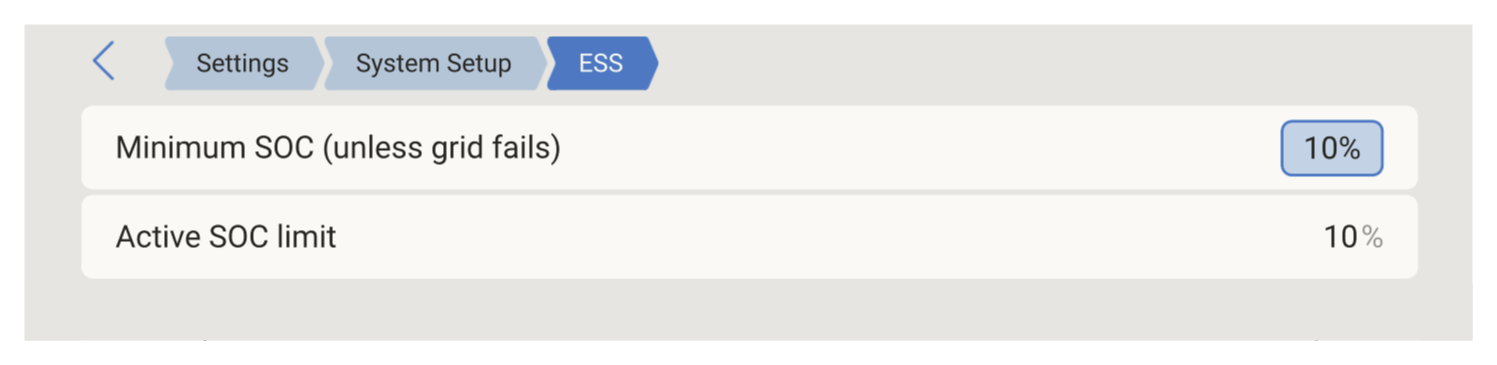 |
5.9. BatteryLife state
BatteryLife state: Displays the current BatteryLife state. This is only shown in Optimized with BatteryLife mode. The possible states are:
See BatteryLife for a full explanation of these states. | 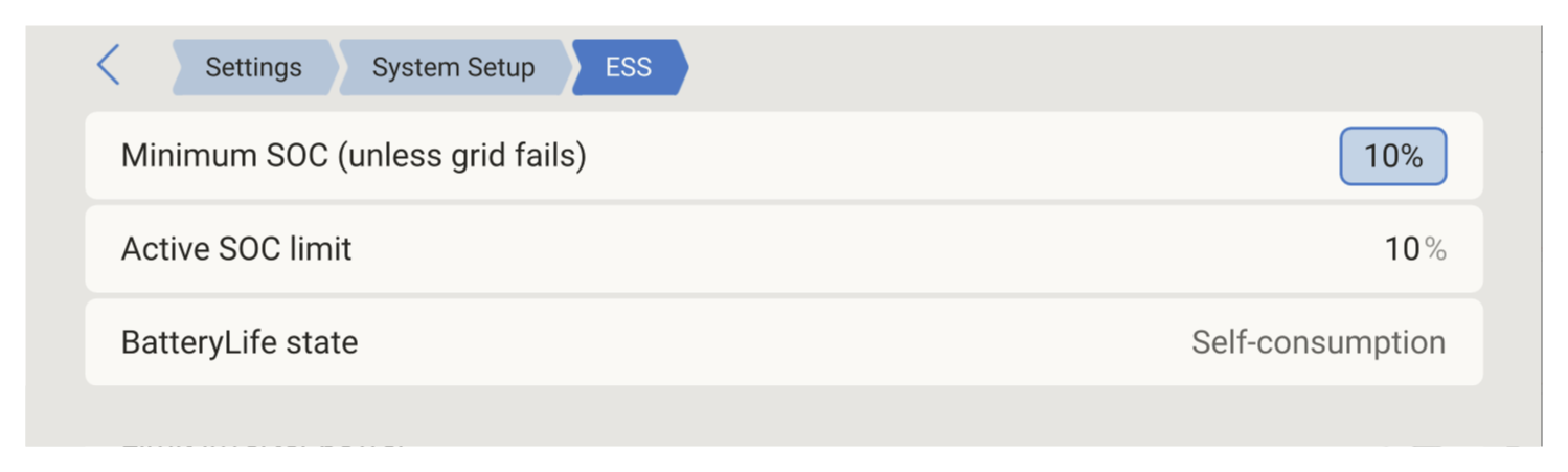 |
5.10. Limit charge power
Limit charge power: Limits the charge power, in watts, that the inverter/charger draws to charge the battery. When enabled, the field 'Maximum charge power' appears. Set the maximum power the inverter/charger uses to charge the battery. This setting is available only when DVCC is disabled. When DVCC is enabled, it is not shown, and the system-wide maximum charge current is configured instead under Settings → System Setup → Charge Control → Limit charge current, which applies to all charging devices together. | 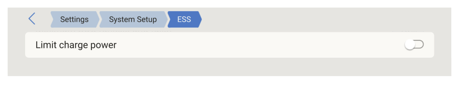 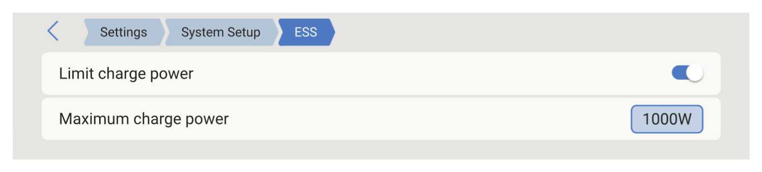 |
5.11. Limit inverter power
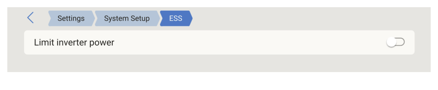
Limit inverter power: Limits the power that the inverter/charger converts from DC to AC. When enabled, a field appears to set the limit.
|  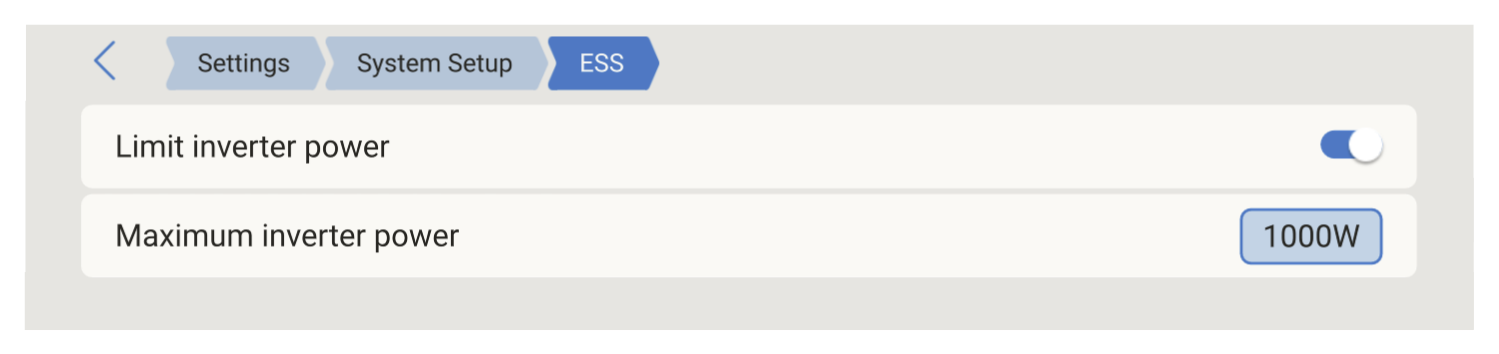 |
Tip
Conversion losses in the inverter/charger are not included in the limit. To limit the power drawn from the battery, set the limit slightly lower than the figure required.
Note
Power coming from the Solar Charger MPPTs is not included in the limit. Using this setting in a system with solar chargers can cause the output power from the solar charger to be reduced.
5.12. Grid setpoint
Grid setpoint: Defines the target power flow at the grid connection point. The system regulates to this value continuously. The default is 50 W, a small positive value. Setting it slightly above zero, rather than at 0 W, provides a buffer that helps prevent unintentional energy export during sudden drops in load. A system regulating to exactly 0 W will tend to overshoot into export when a large load switches off before the system can react; a small positive setpoint keeps the flow drawing slightly from the grid instead. A higher setpoint means the system continuously imports that amount from the grid. A negative setpoint means the system continuously exports, which is not normally desired. | 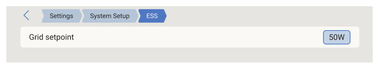 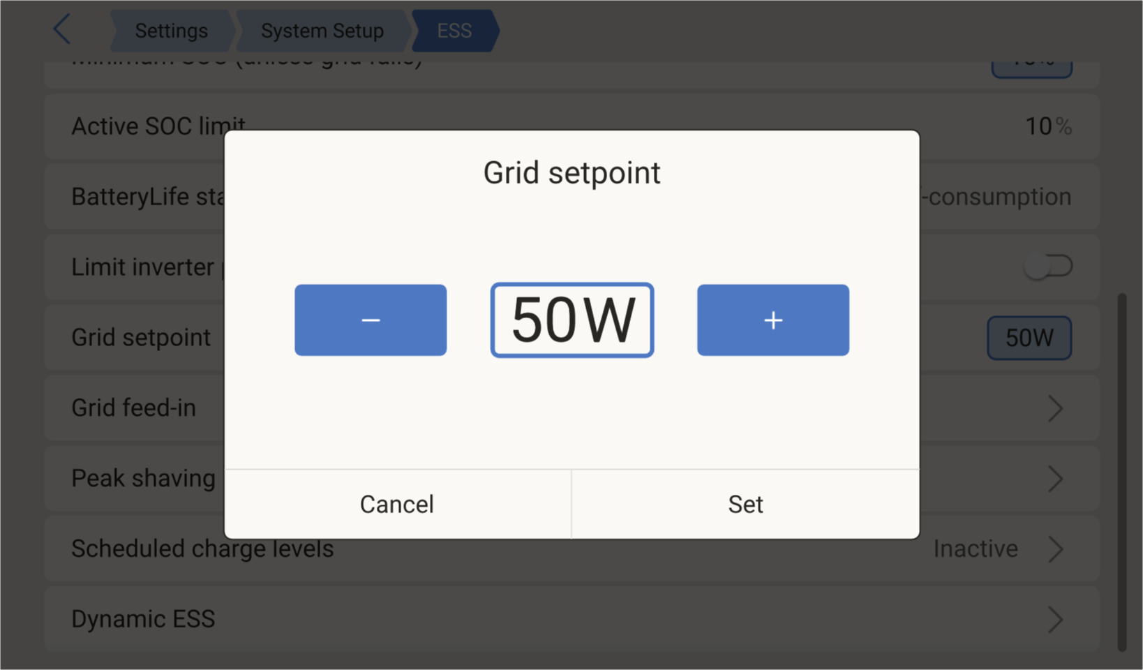 |
5.13. Grid feed-in
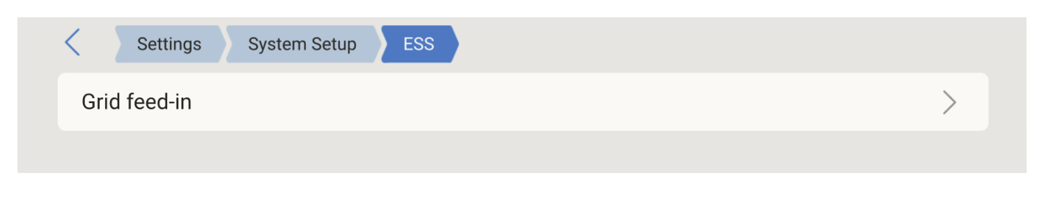
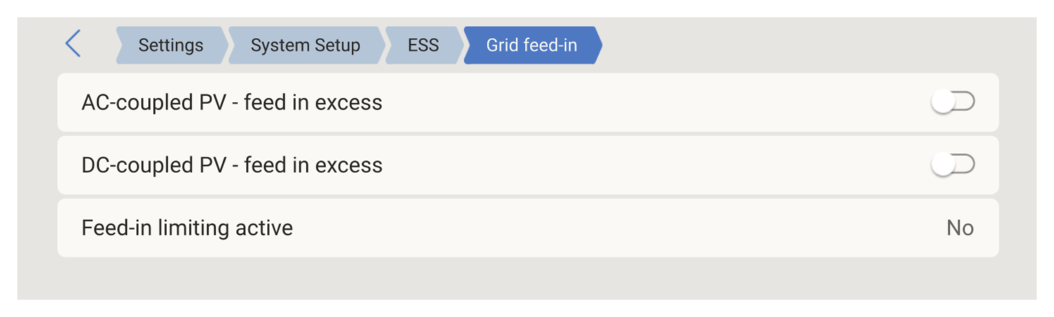
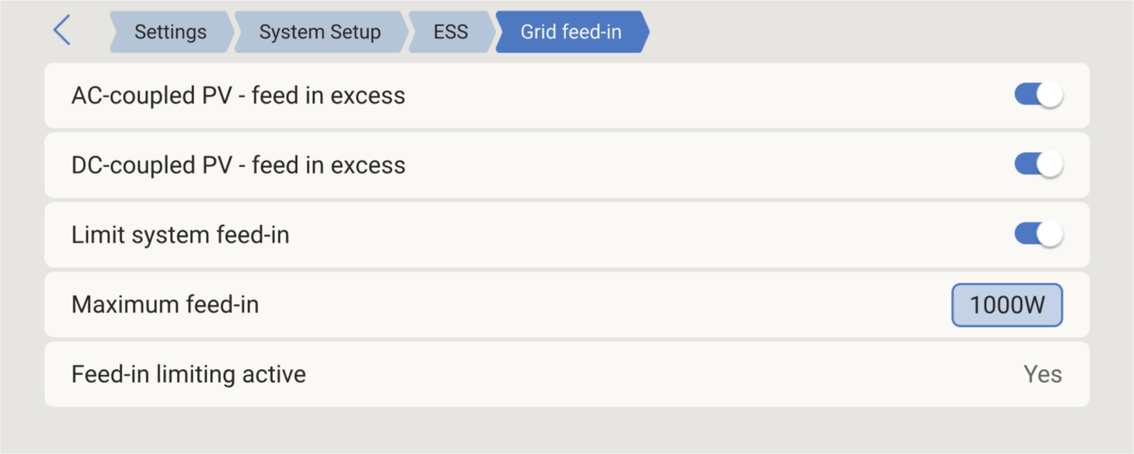
Grid feed-in: Configures how excess solar power is fed into the grid. This is a submenu containing the following items:
|    |
Note
'Limit system feed-in' is a system target. Under some conditions, such as a large load disconnecting or a sudden increase in solar production, the actual feed-in may briefly exceed the target until the system regulates the inverter output back within the limit.
5.14. Peak shaving
Peak shaving limits the power drawn from, or fed into, the utility grid at the grid connection point. When demand exceeds the configured limit, the battery supplies the difference; when export would exceed the limit, the system reduces solar production and battery discharge. This allows a system to support loads that exceed the capacity of the grid connection, and to operate within a contracted or physically limited grid connection.
With and without a grid meter
Peak shaving is available in two forms, depending on whether the system has a grid meter.
Without a grid meter, peak shaving is performed by the inverter/charger itself, using the AC input current limit. That limit is the threshold for the AC current at the AC-In of the inverter/charger, and it applies to current in both directions, so it also caps the current fed back into the grid. When the loads exceed the limit, the battery supplies the difference. Use this method for peak shaving in any system without a grid meter, including systems that use AC current sensors connected directly to the inverter/charger.
Note
The AC input current limit does not take loads connected in parallel with the inverter/charger into account. In a system that relies on the AC input current limit for peak shaving, install all loads on the AC-Out of the inverter/charger.
With a grid meter, peak shaving acts on the current measured at the grid connection point, using the import and export current limits set on the GX device. It therefore applies to the whole system, including high-power loads installed on the AC-In of the inverter/charger, such as EV chargers and heat pumps. This is the form to use when there are loads on the AC-In side.
Peak shaving: determines when the battery is used to shave peaks.
The following two settings act on the current measured at the grid connection point and require a grid meter. Limit system AC import current: when enabled, the field 'Maximum system import current (per phase)' appears. Set the maximum current to be drawn from the grid per phase. When demand would exceed this limit, the battery supplies the difference. Limit system AC export current: when enabled, the field 'Maximum system export current (per phase)' appears. Set the maximum current to be fed into the grid per phase. When production would exceed this limit, solar production and battery discharge are reduced. | 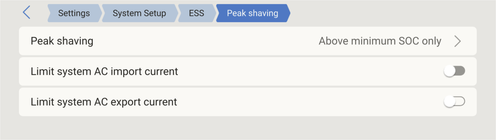 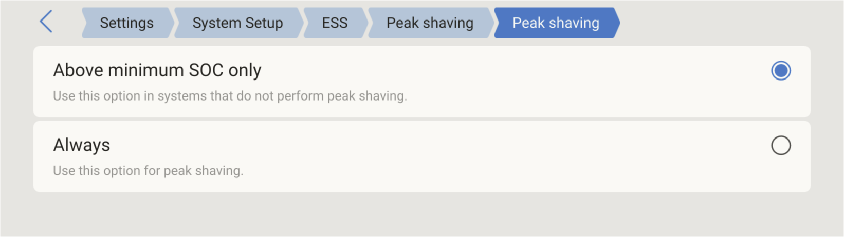 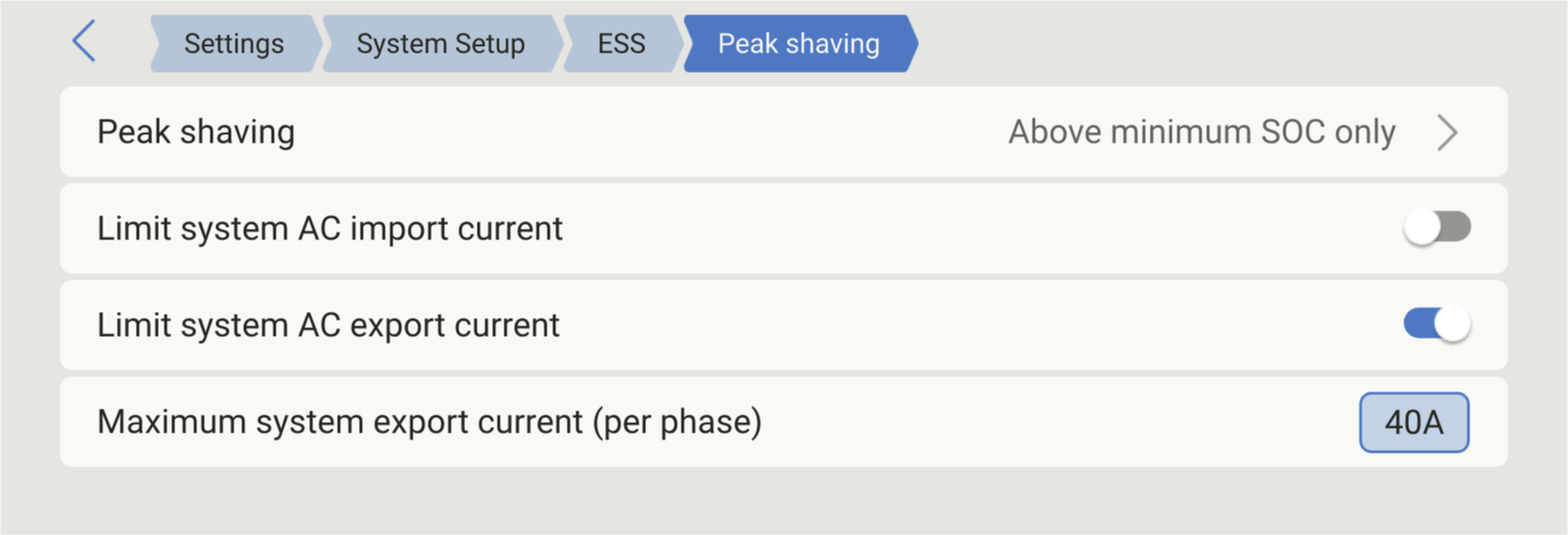 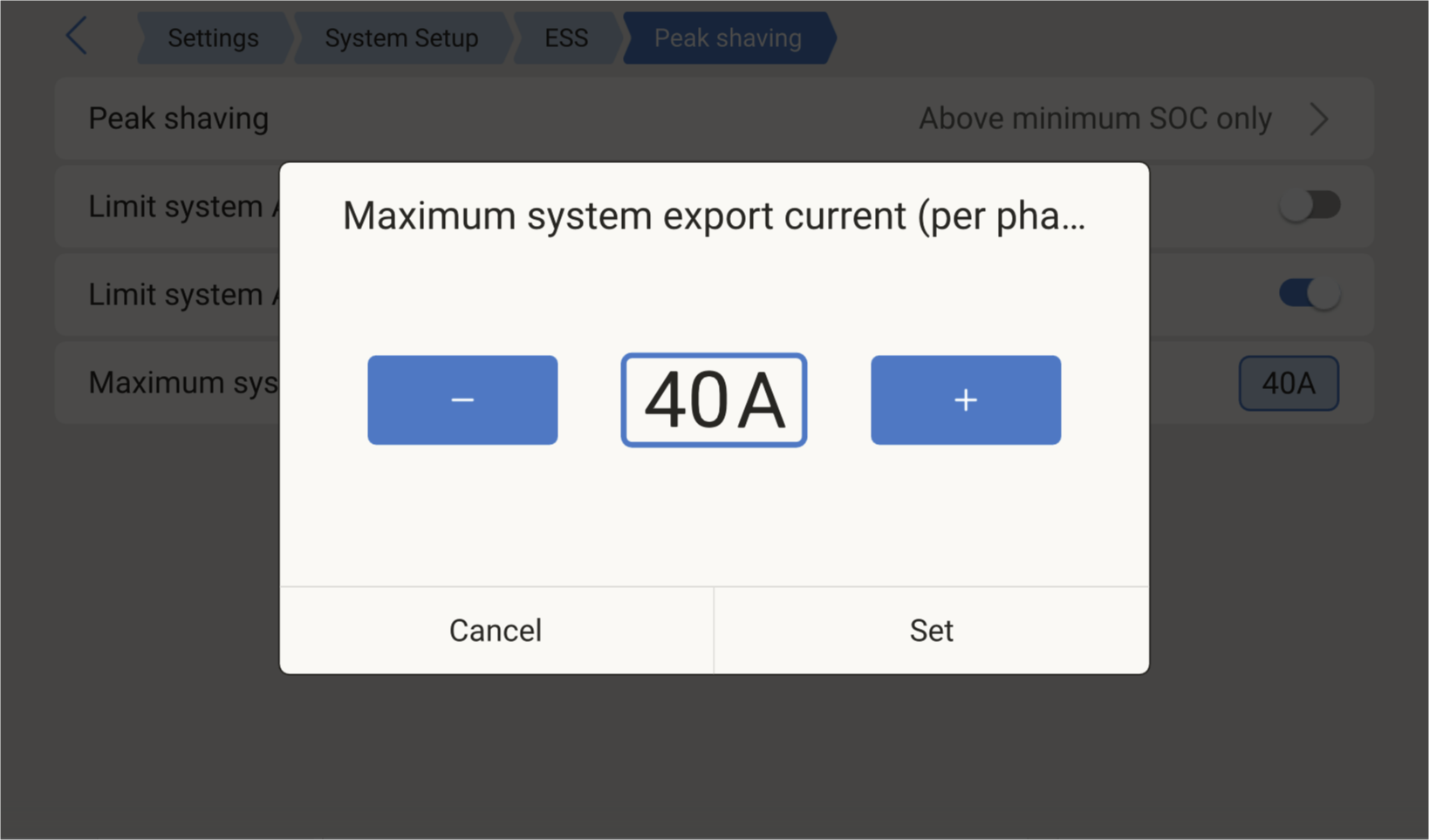 |
How peak shaving works
In an installation with a grid meter, the system continuously monitors the current at the grid connection point and acts to keep it within the configured limits:
To prevent the import limit being exceeded by the loads, the battery assists by supplying the additional power the loads require, for as long as the battery permits.
To prevent the import limit being exceeded, battery charging is reduced.
To prevent the export limit being exceeded, solar production and battery discharge are reduced.
When the SOC has dropped more than 5% below the configured minimum SOC, the battery is recharged from the grid as soon as the loads drop sufficiently to allow charging.
Peak shaving and the Mode setting
Peak shaving operates in all modes, but the way the battery is managed around it differs.
In the Optimized modes, the battery is also used for self-consumption, so its state of charge varies with daily solar and load. Peak shaving draws on the capacity available above the minimum SOC. When the battery reaches the minimum SOC, the system does not force a recharge from the grid; it draws from the grid to cover the loads and relies mainly on solar to bring the state of charge back up.
In Keep batteries charged mode, the battery is held at a high state of charge and is discharged only to shave peaks or during a grid failure. This keeps the full battery capacity available for peak shaving at all times.
Requirements
Peak shaving is part of ESS and is supported on the MultiPlus, Quattro, MultiPlus-II and EasySolar inverter/chargers.
The system requires ESS Assistant version 018C or later. The Assistant is configured in VEConfigure, which requires a trained installer.
The PowerAssist setting in VEConfigure is disabled and ignored when the ESS Assistant is installed.
The Limit system feed-in setting is configured in watts, while the export current limit is configured in amps. When both are set, the lower of the two is applied to the feed-in of DC-coupled PV.
The GX device does not limit PV inverters in response to the export current limit. The PV-inverter system must be configured so that it cannot, by itself, exceed the rating of the grid connection.
Peak shaving with a grid meter works with all grid meters supported by ESS.
Three-phase systems
In three-phase systems, peak shaving interacts with the way the system regulates power across the individual phases. For details of this behaviour, see Multiphase regulation.
5.15. Scheduled charge levels
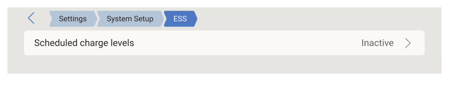
Scheduled charge levels allow the battery to be charged from the grid during defined time windows. Up to five schedules can be configured, each defining a day or day pattern, a start time, a duration, and a target state of charge. This is typically used to charge the battery during off-peak tariff windows (time-of-use tariffs), to prepare the battery ahead of a known grid outage, or to give the battery a regular maintenance charge.
Scheduled charge levels are only available when Mode is set to one of the Optimized modes. They have no effect in Keep batteries charged mode, where the battery is already held at a high state of charge.
How it works
At the start time, the inverter/charger begins charging the battery from the grid. Charging continues until the duration elapses or the SOC limit is reached, whichever comes first. The period defined by the day, start time and duration is referred to as a scheduled charge window.
While a scheduled charge window is active, the ESS state on the Overview page indicates that scheduled charging is in progress. | 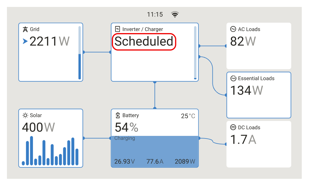 |
Planning multiple schedules
Schedules can be combined to shape battery use across the day. For example, a schedule with a lower SOC target following one with a higher target allows the battery to be used down to the lower state of charge between the two windows.
This is useful when planning around known outages, such as published load-shedding schedules. For example, with outages scheduled at 8pm and again at 4am, the battery can be recharged after the 8pm outage but left to rely on PV after the 4am outage, since solar production will resume shortly afterwards.
Configuring a schedule
Each schedule contains the following settings:
|  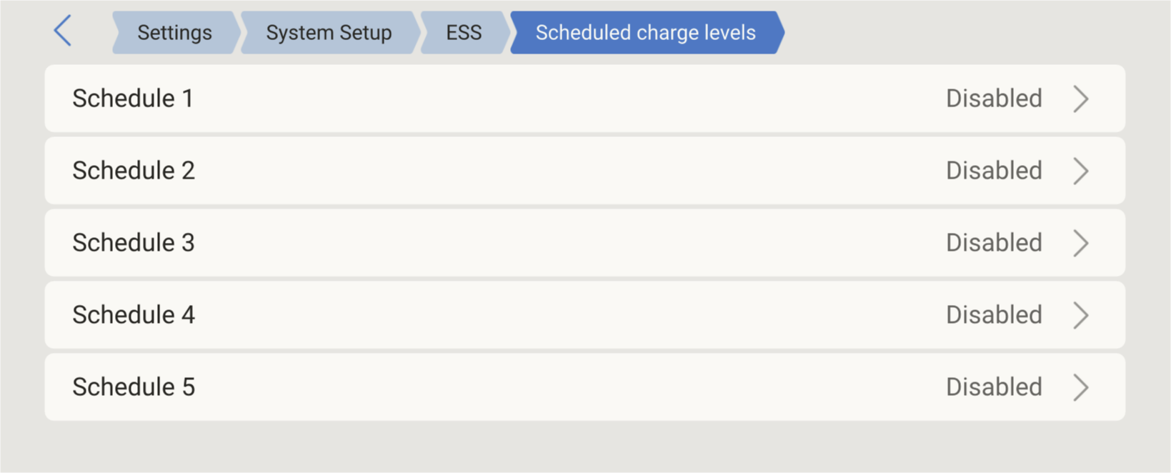 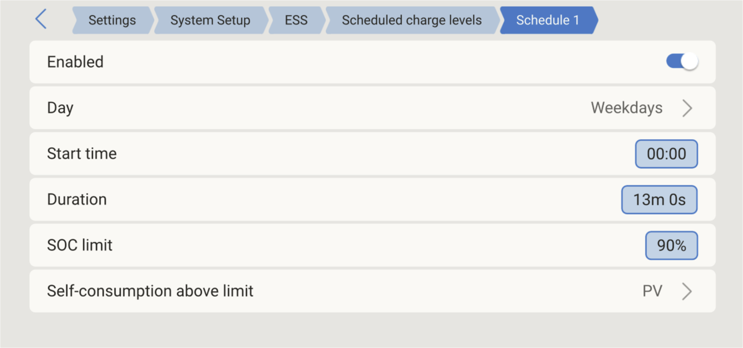 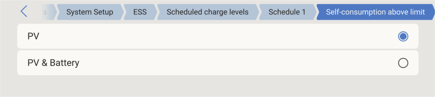 |
5.16. Dynamic ESS
Dynamic ESS optimises the system against a variable or dynamic energy tariff, scheduling battery charging and discharging to minimise energy costs while respecting the configured battery and grid limits.
For configuration and full details, see the Dynamic ESS manual.
5.17. Opportunity Loads
Opportunity Loads increases self-consumption by automatically using surplus solar energy to power flexible AC loads, such as EV charging, heat pumps, water heating and thermal storage, pool pumps and e-bike charging. Rather than curtailing excess PV, or exporting it when feed-in is limited or unattractive, the GX device directs that surplus into useful work.
The GX device acts as a system-level energy coordinator. It continuously reacts to PV production, battery charging requirements, household consumption, available inverter capacity and grid availability, and allocates whatever surplus is available across the supported devices on a priority basis.
How a load is driven depends on the device. The charge current of a supported EV charging station is adjusted to track the surplus available. Other loads are switched on and off: the power the load draws is configured, and the load is switched on once the surplus is enough to cover it.
Because control is centralised in the GX device, several loads can be coordinated together, including multiple EV chargers. This avoids the conflicts that arise when devices run their own independent surplus-charging algorithms.
Supported devices are the Victron EV Charging Station and EV Charging Station NS, and Shelly devices that provide switching and energy measurement. A load with no control interface of its own is switched through one of these devices.
To be used with Opportunity Loads, an EV Charging Station must be connected to the GX device over the MQTT integration. Existing installations that use Modbus TCP can be migrated.
Opportunity Loads requires Venus OS v3.80 or later. The controls are available only in the new GX user interface.
Note
Opportunity Loads and Dynamic ESS cannot be enabled at the same time. Both manage energy at the system level and need control over how energy is allocated, so only one can be active: Dynamic ESS optimises energy flows against electricity prices and forecasts, while Opportunity Loads optimises the local use of surplus solar by controlling flexible loads.
For supported devices, requirements, and configuration, see the product manual for the GX device in use.
5.18. Solar charge controllers (SmartSolar or BlueSolar MPPT)
With ESS, the solar charge controllers:
follow the charge curve set in VEConfigure, or
are externally controlled by an intelligent battery connected via CAN-bus.
Any charge parameters configured on the controllers themselves are ignored.
Note
When using a SmartSolar MPPT with a VE.Can port, ensure the Device instance is set to 0 (the default). Solar charge controllers on the VE.Can network that are set to a different Device instance are not managed by ESS.
5.19. Zero and limited feed-in with PV inverters
Some utilities do not permit export to the grid, or cap it at an agreed level. Where the PV is AC-coupled, keeping within that limit means reducing the output of the PV inverter itself. Limit system feed-in caps the total power fed into the grid, for both AC-coupled and DC-coupled feed-in. For that cap to take effect on AC-coupled PV, the PV inverter must be one the GX device can control, and it must be configured to accept that control. The sections that follow describe the supported PV inverters and the settings each requires.
5.19.1. Fronius PV inverters
The AC-coupled PV zero and limited feed-in feature is specifically designed and most rigorously tested with Fronius AC PV inverters. By using the Power Reduction feature in Fronius grid-tie inverters, the system can automatically reduce the output of the Fronius inverter to prevent or limit export to the grid.
Note the following:
The earliest Fronius firmware version that can be used is 3.7.3-2.
If more than one Fronius PV inverter is present in the system, all of them are limited.
Zero feed-in is not supported on Fronius IG Plus inverters.
Connect the Fronius PV inverter and add it to the GX device. See AC-coupled PV with Fronius PV Inverters for detailed guidelines.
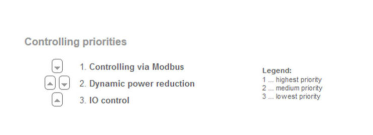
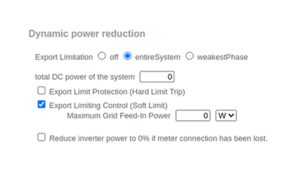
Change the following settings in the Fronius Datamanager web interface:
| 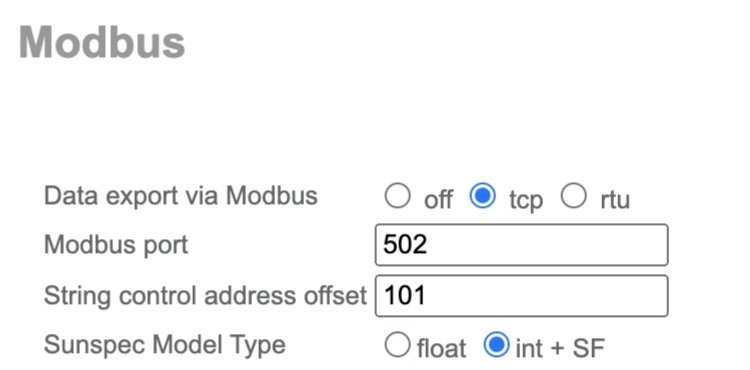 |
|  |
|  |
Checking operation
When the feature is working correctly, the Feed-in limiting active status in the ESS menu shows Yes. If it shows No, check that all of the above criteria are met. Feed-in limiting active shows No if the firmware requirement, the data export, or the Sunspec Model Type settings are incorrect, if the units are shut down (no available PV), or if the AC input is disconnected or unavailable. | 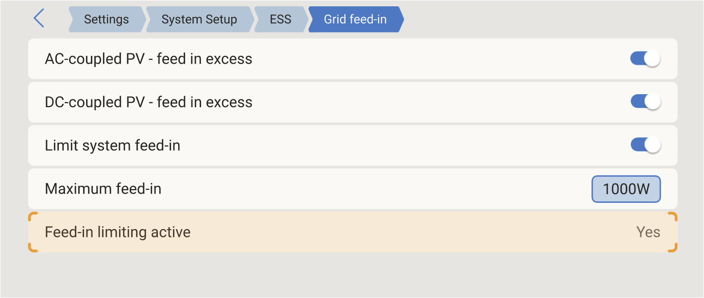 |
Note
Do not use a Fronius Smart Meter for limiting export where ESS is used. ESS already provides the required metering. For details of when a Fronius Smart Meter can and cannot be used, see AC-coupled PV with Fronius PV Inverters.
5.19.2. ABB/FIMER PV inverters
Compatible ABB/FIMER PV inverters can also be controlled by the system so that the export to the grid can be prevented or limited.
Connect the ABB/FIMER PV inverter and add it to the GX device. See CCGX & ABB/FIMER PV Inverters for detailed guidelines.
Checking operation
When the feature is working correctly, the Feed-in limiting active status in the ESS menu shows Yes. If it shows No, check that the PV inverter is configured properly. Feed-in limiting active shows No if the firmware requirement, the data export, or the Sunspec Model Type settings are incorrect, if the units are shut down (no available PV), or if the AC input is disconnected or unavailable. | |
5.19.3. Other PV inverters
A number of SunSpec-compliant PV inverters can also be controlled by the system. Contact a Victron Energy dealer / installer or see Victron Community for details.