8. Commissioning
Commissioning confirms that a correctly installed and configured system behaves as intended under real operating conditions. Before starting, complete the installation and configuration described in the previous chapters. Work through the checks below that apply to the system, simulating each scenario and confirming the expected result.
Communication of the devices
Check and validate that all installed devices are displayed properly on the GX device.
Initial check - normal operation
With the grid connected and the system configured, confirm on the GX device that:
each MPPT solar charger shows External control in its state, and its blue Bulk LED flashes briefly every four seconds, confirming it is remotely controlled by the system;
if a grid meter is fitted, it appears in the Device list;
the battery charges when surplus PV is available, and the grid power reading sits close to the grid setpoint. A slight fluctuation is acceptable.
Scenario - grid outage
Switch off the grid supply at the breaker or isolator to simulate a grid failure. Confirm that:
the system switches to inverter mode without interrupting the loads on AC-Out;
the loads on AC-Out continue to be powered from the battery, and from PV when available, as long as the battery has sufficient charge;
the loads on AC-In are no longer powered. For anti-islanding safety, loads on the AC-In side are always disconnected during a grid outage.
Switch the grid back on and confirm that the AC-In loads are powered again and the system returns to normal operation.
Scenario - self-consumption of AC-In loads (grid connected)
This check verifies how the battery supplies loads on the AC-In side while the grid is connected. The behaviour depends on Settings → System Setup → ESS → Self-consumption from battery and Settings → System Setup → AC System → Position of AC loads. With the grid connected and a load running on the AC-In side:
with Self-consumption from battery set to All system loads, confirm that the battery discharges to supply the AC-In load;
with Self-consumption from battery set to Only critical loads, confirm that the AC-In load is supplied from the grid and the battery is not discharged to supply it.
For the battery to supply AC-In-side loads, Position of AC loads must be set to include the AC input.
Scenario - loss of PV power
Simulate a sudden drop in solar production, for example by covering the array or waiting for cloud cover. Confirm that:
the system smoothly increases the power drawn from the battery, and from the grid if required, to continue supplying the loads;
there is no interruption to the loads as PV production falls.
Scenario - high load / peak demand
Switch on a load larger than the available PV and grid setpoint. Confirm that the battery supplies the additional power required and that the loads remain fully powered.
Scenario - reaching minimum SOC
Allow the battery to discharge to the configured minimum SOC, or simulate this condition. Confirm that discharging stops at the minimum SOC and the loads are then supplied from the grid.
Keep batteries charged mode
If the system is set to Keep batteries charged mode, confirm that the battery begins charging immediately after the mode is configured, and that it charges from both the grid and PV.
Backup generator
If a generator is fitted, start it and confirm that the system begins charging the battery.
Zero feed-in with supported PV inverters
If the system uses a supported PV inverter with zero feed-in, confirm that Feed-in limiting active shows Yes in the Settings → ESS menu.
8.1. LED codes during ESS operation
When the inverter/charger operates in parallel with the grid, as it does when ESS is used, the Mains and Inverter LEDs indicate the direction of power flow. The table below describes the relevant LED codes, including some combinations that are not specific to parallel operation with the grid. LED indications not listed here are covered in the inverter/charger manual.
Mains and Inverter LED states | Description and power direction |
|---|---|
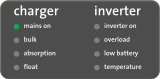 | Power flowing to the battery (normal charging) |
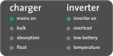 | Power flowing to the loads (similar to PowerAssist) |
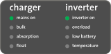 | Around the balance point |
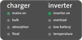 | Power flowing to the grid |
Remaining combinations, not specific to parallel operation with the grid | |
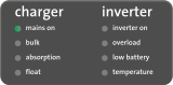 | The unit is set to charger-only mode but is still off. Grid voltage is detected but has not yet been accepted. |
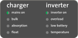 | The unit is a slave (LEDs blink slowly and alternately) |
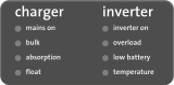 | The unit is off |
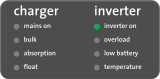 | Inverter mode |
 | LED on LED blinking LED off |